Detailed Description
AMSAT-OSCAR 7 was launched November 15, 1974 by a Delta 2310 launcher from Vandenberg Air Force Base, Lompoc, California. AO-7 was launched piggyback with ITOS-G (NOAA 4) and the Spanish INTASAT. and was the second Phase 2 satellite (Phase II-B).
Weight: 28.6 kg.
Orbit: 1444 x 1459 km.
Inclination: 101.7 degrees.
Octahedrally shaped 360 mm high and 424 mm in diameter.
Circularly polarized canted turnstile VHF/UHF antenna system and HF dipole.
Similar to AO-6. Built by a multi-national (German, Canadian, United States, and Australian) team of radio amateurs under the direction of AMSAT-NA. It carried Mode A (145.850-950 MHz uplink and 29.400-500 MHz downlink) and Mode B (432.180-120 MHz uplink and 145.920-980 MHz downlink (inverted)) linear transponders and 29.500 and 145.700 MHz beacons. The 2304.1 MHz was never turned on because of international treaty constraints.
Four radio masts mounted at 90 degree intervals on the base and two experimental repeater systems provided store-and-forward for morse and teletype messages (Codestore) as it orbited around the world. The Mode-B transponder was designed and build by Karl Meinzer, DJ4ZC and Werner Haas, DJ5KQ. The Mode-B transponder was the first using “HELAPS” (High Efficient Linear Amplification by Parametric Synthesis) technology was developed by Dr. Karl Meinzer as part of his Ph.D.
Spacecraft Description
AMSAT-OSCAR 7 contains two basic experimental repeater packages, redundant command systems, two experimental telemetry systems, and a store-and-forward message storage unit. The spacecraft is solar powered, weighs 65 pounds, and had a three-year anticipated lifetime at the time it was launched, but it has far outlived this expectation. It contains beacons on 29.50, 145.975, 435.10 and 2304.1 MHz.
Communications Repeaters
Two types of communications repeaters are aboard the spacecraft, only one of which operates at a time. The first repeater is a higher power, two-watt version of the one-watt two-to-ten meter linear repeater that flew on the OSCAR 6 mission. This non-inverting transponder receives uplink signals between 145.85 and 145.95 MHz, and retransmits them between 29.4 and 29.5 MHz on the downlink. A 200 milliwatt telemetry beacon provides telemetry data on 29.502 MHz. Approximately -100 dBm is required at the repeater input terminals for an output of 1 watt. This corresponds to an EIRP from the ground of 90 watts for a distance to the satellite of 2,000 miles and a polarization mismatch of 3 dB.
The second repeater, constructed by AMSAT Deutschland e.V., AMSAT’s affiliate in Marbach, West Germany, is a 40-kHz* bandwidth inverting linear repeater. It employs an 8-watt PEP power amplifier using the envelope elimination and restoration technique to maintain linear operation over a wide dynamic range with high efficiency. This repeater has an uplink from 432.125 to 432.175 MHz, and a downlink from 145.975 to 145.925 MHz. Since the uplink band in shared with the radiolocation service, an experimental pulse suppression circuit is incorporated in the repeater to reduce the effects of wideband pulsed radar interference in the uplink. Developmental versions of this repeater have flown in high-altitude balloon experiments in Germany, and aircraft flight tests of the repeater prototype unit. A 200 milliwatt telemetry beacon on 145.975 provides telemetry data. Approximately 50 watts EIRP is required to produce 3 watts of repeater output at a range of 2,000 miles assuming a polarization mismatch of 3 db.
The two repeaters are operated alternately by means of a timer arrangement, but repeater selection and output power control can also be accomplished by ground command. Each of the repeaters includes a keyed telemetry beacon at the upper edge of the downlink passband to provide housekeeping data and to provide a frequency and amplitude reference marker to assist the amateur in antenna pointing, Doppler frequency compensation, and setting uplink power level. The cross-band 146-to-29.5 and 432-to-146 design of the two repeaters will permit the amateur to monitor his own downlink signal easily, and consequently, he can adjust his power and frequency to continually compensate for changing path loss, repeater loading and Doppler shift.
Command System
Redundant command decoders of a design similar to the unit proven highly successful in OSCAR 6 were flown. The decoder has provisions for 35 separate functions, and is designed to provide a reliable means of controlling the emissions of the repeaters, beacons and other experiments aboard the spacecraft.
Telemetry and Message Storage Systems
AMSAT-OSCAR 7 contains two experimental telemetry systems designed for use with simple ground terminal equipment. The first system, developed by the WIA-Project Australis group in Australia, telemeters 60 parameters in 850-Hz shift, 60 WPM five-level Baudot teletype code to permit printout on standard teletype equipment in a format readily convertible for direct processing by small digital computer. The second system telemeters 24 parameters as numbers in standard Morse code and can be received with pencil and paper. This system was used on OSCAR 6 and proved highly successful as a reliable means of obtaining real-time telemetry data.
An experimental Morse code message storage unit, Codestore, capable of storing and repeatedly retransmitting 18-word Morse code messages loaded by ground stations is also aboard AMSAT-OSCAR 7. This unit was first flown on OSCAR 6. This unit is not currently in use, and it is unclear if it is still operational.
The teletype telemetry encoder amplitude-modulates telemetry beacons on 29.50 MHz (200 mW), 145.98 MHz (200 mW) and frequency-shift keys the beacon on 435.10 MHz (300-400 mW), as selected by ground command. The Morse code telemetry encoder and Codestore message storage unit directly key these beacons as selected by ground command. However, at the present time, the satellite is not being actively commanded by a ground station, so these telemetry systems are not being activated.
Current Operational State
AO-7 became non-operational in mid 1981 due to battery failure . In 2002 one of the shorted batteries became an open circuilt and now the spacecraft is able to run off solar panels. For this reason it is not usable in eclipse and may not be able to supply enough power to the transmitter to keep from frequency modulating the signal. When continuously illuminated, the mode will alternate between A and B every 24 hours.
Mode V/A (A) Linear Transponder (Non-Inverting):
Uplink: 145.8500 – 145.9500 MHz SSB/CW
Downlink 29.4000 – 29.5000 MHz SSB/CW
Mode V/A (A) TLM Beacon:
Downlink 29.5020 MHz CW
Mode U/V (B) Linear Transponder (Inverting):
Uplink: 432.1250 – 432.1750 MHz SSB/CW
Downlink 145.9750 – 145.9250 MHz SSB/CW
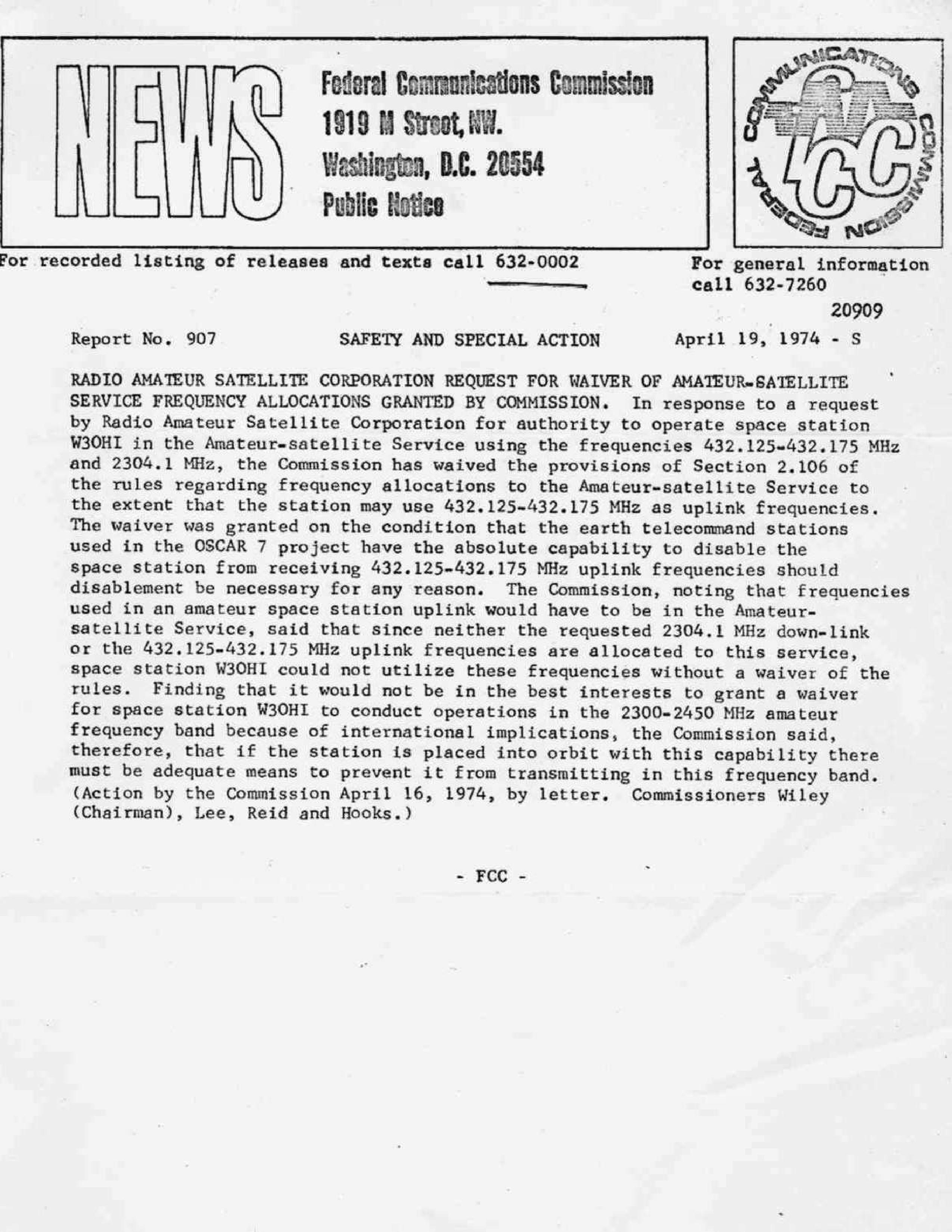
(Note: The 432 MHz uplink on AO-7 was designed before implementation of the 435-438 MHz satellite subband. Operation in the US is currently grandfathered under a waiver from the FCC, included at the bottom of this page.)
Mode U/V (B) TLM Beacon:
Downlink 145.9775 MHz CW
Mode U TLM Beacon
Downlink 435.1000 MHz CW
For more detail, see the AMSAT-OSCAR 7 Technical Operations Plan And Experimenter’s Guide.
 :
: