James Miller G3RUH
A chance flit through an article [1] on the recovery of Giotto (to ready it for another mission) included an interesting comment. "You should never mount your antenna straight on a spinning spacecraft; you put it offset so you can see the doppler". In a flash I had an idea.
The AO-13 mode-S antenna is mounted off centre. So, when squint angle is not exactly zero, the antenna must appear to the observer to be moving back and forth along the line-of-sight cyclically by a few tens of cm. This is a significant fraction of a wavelength at 2.4 GHz, and must show up as phase modulation on the beacon or a transponded carrier.
So it should be detectable as beacon FMing. If we measure the deviation of that FM, since it is proportional to the magnitude of the 'wobble', we can calculate Squint angle directly!
This also offers us a system of attitude measurement totally independent of Sun and Earth sensors, optics and the like.
Furthermore, the technique and its variations would be extremely useful for the forthcoming P3D satellite. Why didn't I think of this years ago? Thus excited, I embarked on some experiments that anyone can duplicate.
Assiduous telemetry readers or even transponder hackers may have noticed the S-band system was switched on at odd times during December 1992. This was to enable calibration to take place.
Sure enough, at a squint of 90 deg, the FMing is maximised at about 21 Hz peak-peak. Amazingly, though the high gain S-band antenna was by definition sideways on, admittedly at a range of only 10,000 km, there was a clear return on my 60 cm dish. Freddy ON6UG assisted in these tests, at considerable personal in-convenience, using his 2m dish and a pen recorder. Could you have got up at 3 a.m. several nights running to do this? A very big thank you to Freddy!
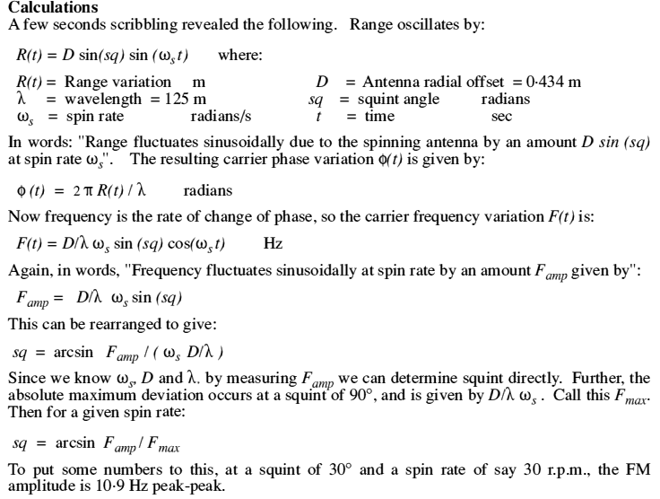
Figure 1. shows a typical output from my own processing software. Rather than manually read the voltage off a 'scope (very tedious), I connected the PLL VCO voltage directly to the ADC card of my computer and read the value that way at a rate of 100 samples/sec. Once the data is captured in a computer, it is infinitely easier to manipulate.
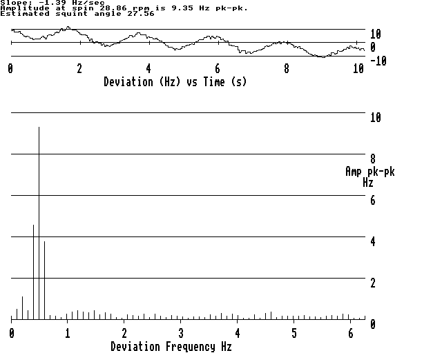
Figure 1. Oscar-13 Mode-S Transponder FM characteristics. Steady carrier uplinked, and PLL VCO voltage displayed. Received frequency deviation is F(t) = d ws Sin (sq) Cos (ws t) Hz where d is the antenna offset in wavelengths, ws is spin-rate in radian/s and sq is squint angle. Fourier transform aids analysis.
The situation was this. A routine attitude change from Alon/Alat 180/0 to 210/0 took place at the end of November 1992. This is a move of 30 deg, and we know that it can be accomplished by the magnetorquers in 4 perigee passes. We also know that re-orientation is somewhat erratic, but 4 perigees activity cannot move us more than 30 deg, so the change was bounded and safe (from the point of view of solar power production).
This indeed proved to be the case, with a new safe attitude achieved, and the solar illumination essentially as planned.
However we also knew in advance that immediately after the change the Earth sensors would be blinded by the Sun for two weeks. So we would have no reliable attitude measurements straight away. We would have to wait a few days for an accumulation of Sun data only.
Directly after the change, we realised that we had experienced one of the random walks that the AO-13 magnetorquing process sometimes presents us. During mode-L and mode-S transponder operation, the spin modulation was found to be appalling. Even the mode-B transponder was a relatively hard slog, and at only 25,000 km. My calibrated "golden" ears told me that the squint angle was 30 deg or more, which suggested the orientation was perhaps 20-30 deg off the planned direction.
These odd outcomes are common, and easily dealt with by a simple correction magnetorque, if you know where you are. And as noted above, immediately after the change, we could not.
There was nothing to do but wait. After about 4 days, we would have enough Sun sensor data to compute an attitude. This was duly done, and suggested an attitude solution Alon/Alat 214/10 (although with a large computational uncertainty). We did not believe this reduction, for if correct, it would have meant reasonable squint angles during mode-L and mode-S. And as remarked, they were in fact perfectly dreadful.
We waited anxiously once again for some resolving Earth sensor data. When it finally came, after 10 days, we couldn't believe what we saw! It was again totally inconsistent with our expectations.
During this fortnight of fretting, I had hit upon the idea of direct squint measurements. So it was with a great deal of excitement that we anticipated our first results. When we got them, we were absolutely delighted. Yes indeed the squint angle was 28 deg during mode-S! A few more confirming measurements were made. The plot of figure 2 resulted. This is the graphical output from a program called ATTPLOT that is used to determine AO-13 attitude from multiple sensor observations.
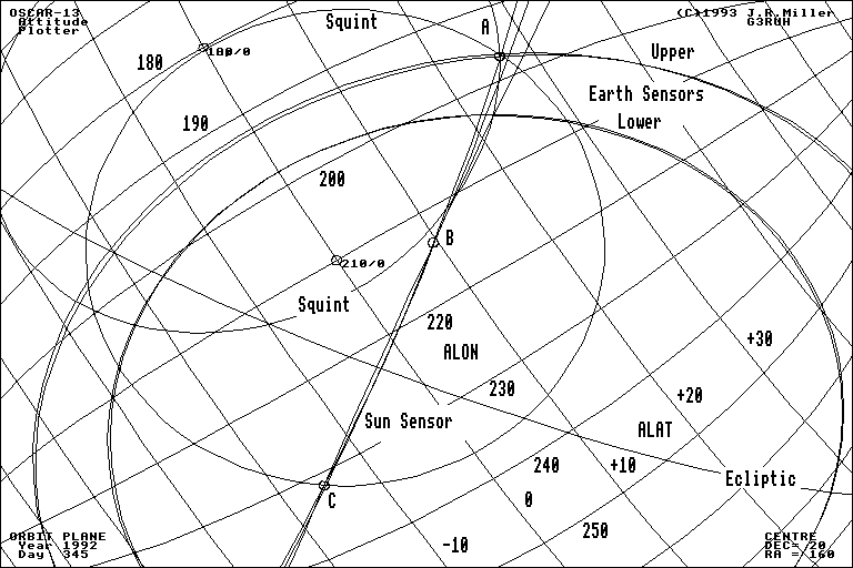
Figure 2. AO-13 attitude determination plot, 1992 Dec 10. This shows graphically how direct measurements of squint angle revealed that the attitude direction was given by point A, and not points B or C as initially expected. B and C are false solutions because unusually the spin axis orientation had changed slightly during data collection. Probably caused by buffeting during perigee fly-by, height 620 km.
Our conclusion was that the attitude direction was in fact Alon/Alat 196/27, marked as point A. Hardly the planned value of 210/0 !
The important thing about this plot is that, under normal circumstances, all data lines should intersect at one point. That is, the three Sun lines, the upper and lower Earth sensor lines, and the two Squint lines should converge at 196/27. That they do not is, with 100% hindsight, because a) the lower Earth sensor was giving invalid data at the time, and b) what we have long suspected, the spin axis direction sometimes wanders due to buffeting during its low perigee encounters. That's why the Sun sensor data doesn't converge at A but gives falsies B and C.
That the Squint lines, upper Earth sensor and newest Sun line do intersect properly at A is regarded as a triumphant success for this new method. Furthermore, the next attitude change in 1993 January was planned using this determination, and executed perfectly. Imagine what would have happened if the seductive solution C had been adopted!
Feedback on these pages to Webmaster. Feedback on the article should be sent to James Miller
Created: 1995 Feb 11 -- Last modified: 2023 Apr 13