

James Miller G3RUH
Data bits in Oscar-13's memory get corrupted from time to time. If this were to happen in your home computer, it would almost certainly "crash". Yet AO-13's computer carries on unaffected. How do we know that memory bits get flipped? What is the physical construction of the memory? How does the machine take corrective action? How has it performed over six hard years? And why the ambiguous title? Oscar-13 has a 32 kbyte memory provided by 6 Harris HM6564 SRAM hybrids. Each HM6564 package contains 16 Harris 6504 4k x 1 dies, arranged as 16k x 4 bits. So the total memory is 32k x 12 bits. These 12 bits comprise the normal 8 bit byte, plus 4 vital parity bits that are used for EDAC (error detection and correction). With this arrangement, each 12 bit byte is spread across 12 memory dies spatially separated by large (in semiconductor terms) distances. This ensures that it is extremely unlikely a radiation "hit" will corrupt more than one bit in the same byte. The memory chips are radiation hardened, cost a small fortune, and were donated to AMSAT by Harris Semiconductors. Further radiation resistance is achieved by surrounding the 6564 chips by a box with thick metal walls and lids of sheet tungsten. To WRITE a byte to memory, it is first passed to the EDAC circuit which generates the 4 extra parity bits, and then all 12 bits are written. On READ, 12 bits are read out, passed again through the EDAC logic which corrects single bit errors. The validated 8 bit byte is then sent to the computer. If an error is detected a hardware counter is also incremented. Periodically (once per MA count) this counter is checked for a change, and if so a flash block of telemetry is stored in the "event buffer". This holds sixteen such events, and they are sent down in rotation in the 512- byte PSK "Q" blocks in byte positions 256-383, just before the live telemetry, bytes 384-511. A read operation doesn't however replace the corrected byte in memory. Instead this function is performed explicitly by software later. Every 20 ms, 16 bytes are read out of memory and written back again with correction if necessary. This "wash" operation cleans up 32k of memory every 40 seconds. EDAC Memory Circuits -------------------- Circuits to perform error detection and correction are delightfully simple. In the following, to keep explanations short, I'm going to assume initially 4-bit data words plus 3 parity bits, which needs a 7 bit wide memory word. (Oscar-13 itself has 4 parity bits, which can protect up to 11 data bits. However it uses only 8 of these, the other 3 being assumed "0".)The WRITE operation is shown in figure 1. The three parity bits are formed from exclusive-ORs of the data bits, viz P0=D0+D1+D3, P1=D0+D2+D3, P2=D1+D2+D3. Then these 7 bits (D0,D1,D2,D3,P0,P1,P2) are written into memory. They are collectively called a "code word". Since there are only 4 data bits there can only be 16 valid code words out the 128 possible 7 bit combinations. This 8-fold extravagance is what makes error control possible. 
The READ operation is shown in figure 2. The parity bits are calculated again from the 4 read data bits and compared with the 3 stored parity bits. Obviously both sets of parity bits should be the same, so the checks (marked S0, S1 S2) should all be 0. However if any one of the read 7 data+parity bits is in error, then one or more of the "S" bits will be set. S0,S1 and S2 are aptly called the "syndrome" because they describe what is wrong with the data. The 3 bit syndrome is decoded in a 1 out of 8 decoder, and then one of these outputs corrects the erroneous bit. To see how this magic works, consider the following table. It's a decoding matrix; the three across rows pick out the relationship between parity bits and data bits. The first row relates P0, and D0, D1, D3, the second P1 and D0, D2, D3, the third P2 and D1, D2, D3, just as indicated in figs 1 and 2. Turn the table on its side, and you should see some familiar patterns! P0 P1 D0 P2 D1 D2 D3 ------------------------------------- S0 . X . X . X . X S1 . . X X . . X X S2 . . . . X X X X ------------------------------------- Q 0 1 2 3 4 5 6 7 ------------------------------------- Suppose for example that data bit D0 gets corrupted. From the "X"s in the table, the parity checks given by rows 1 and 2 (S0,S1) are going to fail, whilst S2 will be OK. Now S2=0, S1=1, S0=1 decodes as "3", which must mean "please correct data bit D0". Notice that all eight syndromes are uniquely associated with one corrupted bit. Formally, in terms of linear algebra, no one row can be formed by modulo-2 addition of any combination of the others. However it is important to note that only one bit at a time can be corrected. If two bits are corrupted, then the wrong syndrome results. For example, suppose P0 and P1 are simultaneously in error, then the syndrome will be S2=0, S1=1, S0=1 which is "3" again, and obviously correcting bit D0 as before will only compound the errors. Syndrome combination "0" means "no error", and is the usual condition. So its unexpected absence can be used to operate an error counter. AO-13's 8 bit Protection ------------------------ As Oscar-13 has eight data bits, the simpler 4 data scheme described is merely extended by an additional parity bit. In principle therefore it's an 11 data + 4 parity system, but three data bits are not implemented, so it's 8+4 = 12 memory bits per byte. You should be able to see by inspection how the table is to be extended. By the way, this single bit error/correction scheme was invented by R.W. Hamming in 1950. AO-13 Performance ----------------- As mentioned earlier, when a memory bit is corrupted it is not only corrected, but a counter is also incremented and a block of telemetry is preserved for later analysis. From this data, charts can be drawn. 
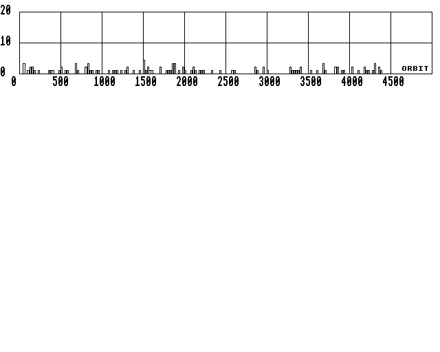
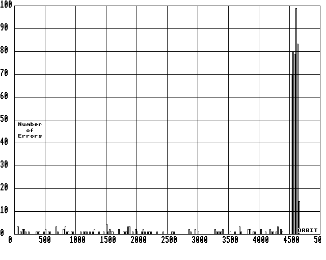
Figure 3 shows the number of memory errors that occurred in each 25 orbit segment up to 1994 May 13. Very thinly distributed indeed. There are even two periods of zero hits in 4 months. In fact, since launch, 1988 Jun 15 to 1994 May 13 there were just 116 memory errors. That equates to an average of 1 error every 39 orbits. This is a remarkable testimony the radiation resistance of the Oscar-13 memory system. Friday the 13th --------------- After 1994 May 13 (a Friday), in the two months up to the time of writing 1994 July 12, things look rather different; see figure 4. 
The memory error rate has shot up by a factor of x100 to an average of 3 per orbit! In the week subsequent to May 13 the software on both LUSAT and ITAMSAT crashed, and KO-23 suffered a similar fate though this may not be related. FO-20 digital mode has also run into problems, though again this may not be related. 
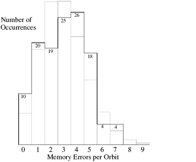
Figure 5 shows a histogram of the the number of orbits that have experienced 0,1,2 ... 9 hits. Superimposed in faint is a Poisson distribution with a mean of 3 events/orbit. A statistical test of their similarity confirms the hypothesis that the hits are random. There is some evidence that the rate fluctuates slightly, as the number of hits per 25 orbit period (figure 4) is a little too scattered for a steady rate. Conclusion ---------- Well, what are we to make of all this? Has the radiation environment suddenly gone "over the top"? Has something deteriorated in the flight computer? Memory chips? EDAC circuits? In truth I am in no position to judge. I just press the buttons, and gather the telemetry. Explanations must come from the sages in these matters. In fact I have but one conclusion. It is this: "Amsat has no potential Phase III command stations coming up through the ranks". Non sequitur? ------------- OK, OK! How does he get from AO-13 increased memory errors to that ludicrous dogma? Simple. The memory error counter has been ramping away at over 100x the normal rate for two months. We have had more hits in those two months than we could have statistically expected in 20 years of normal operation. Everything I have elucidated above is public knowledge. The principles of EDAC systems can be found in 1001 textbooks e.g. [1]. The description of AO-13's specific system is recorded in [2]. Solar flux data, warnings and analysis appear in prolific detail on all the digital networks. And finally AO-13 telemetry is available 24 hours a day for anyone to read. Yet in these eight weeks, not one single person in the whole wide world has noticed or made any comment about the situation whatsoever! Command stations are not made overnight. You don't take someone, plonk a manual (there isn't one!) in front of them, and at the end of a training period expect a fully fledged operator to emerge. It has never worked like that. This is amateur radio. What actually happens is that interested people apply themselves, asking questions, finding out answers and persevering, learning their craft almost imperceptibly, adopting a satellite as a rich source of intellectual and practical endeavour. This process can take as little as a year, but is often longer. But the very act of doing this doesn't go unnoticed. If someone with these inclinations had come forward and asked even the simplest question like "why is this memory error counter racing away?", that in itself might just have been the seed from which a new command station could have been grown and nurtured to maturity. But it didn't happen and, unlike a decade ago, it doesn't happen. Hence my conclusion; Amsat has no potential Phase III command stations coming up through the ranks. What's the solution? References ---------- 1. Haykin, S. "Digital Communications", John Wiley & Sons 1988. ISBN 0-471-62947-2. 2. Miller, J.R.; "Oscar-13 Memories are made of this", Oscar News 1989 Dec, No.80 p.26-28 
Feedback on these pages to Webmaster. Feedback on the article should be sent to James Miller
Created: 1994 Nov 17 -- Last modified: 2005 Oct 29