The KD2BD 9600 Baud Modem
By: John A. Magliacane, KD2BD
 |
The KD2BD 9600 Baud Modem
By: John A. Magliacane, KD2BD |
 |
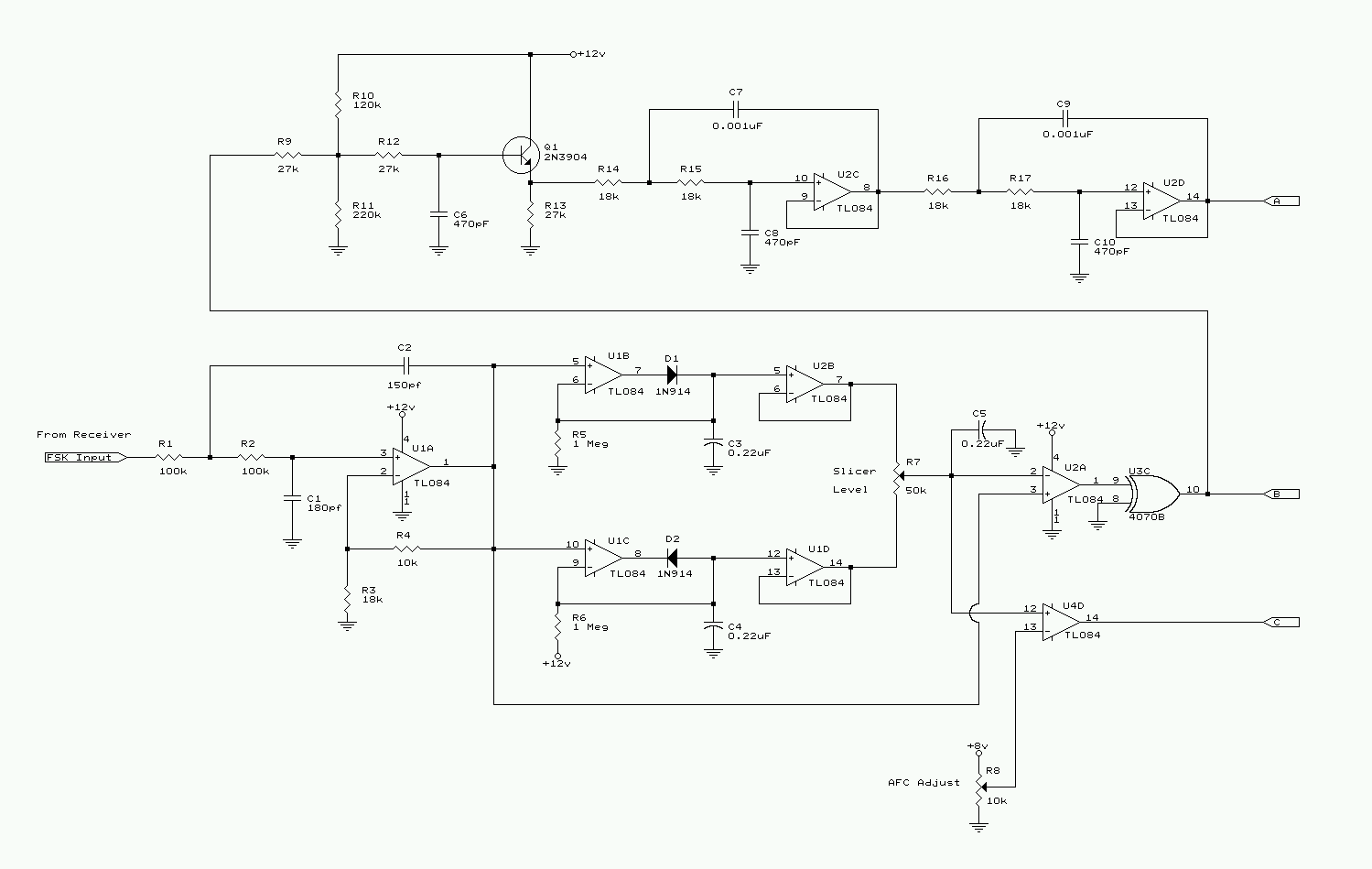
Schematic 1: Input section of the modem showing post detection low-pass filtering and precision peak detectors.
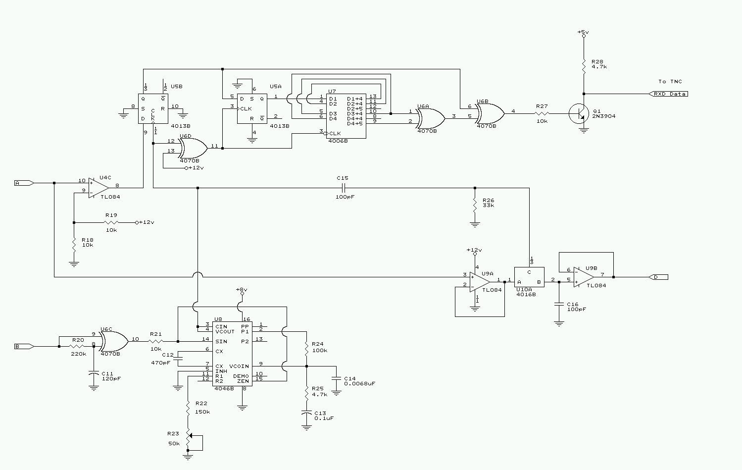
Schematic 2: Receiver bit clock regeneration circuitry and unscrambler.
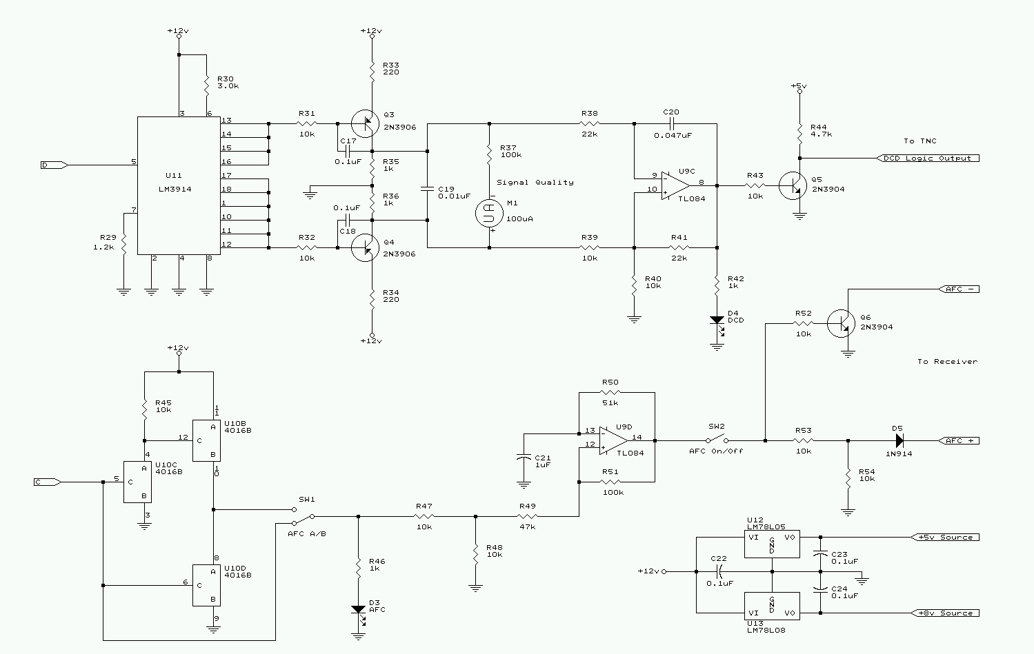
Schematic 3: FSK data carrier detection (DCD) and digital automatic frequency control (AFC) circuitry.
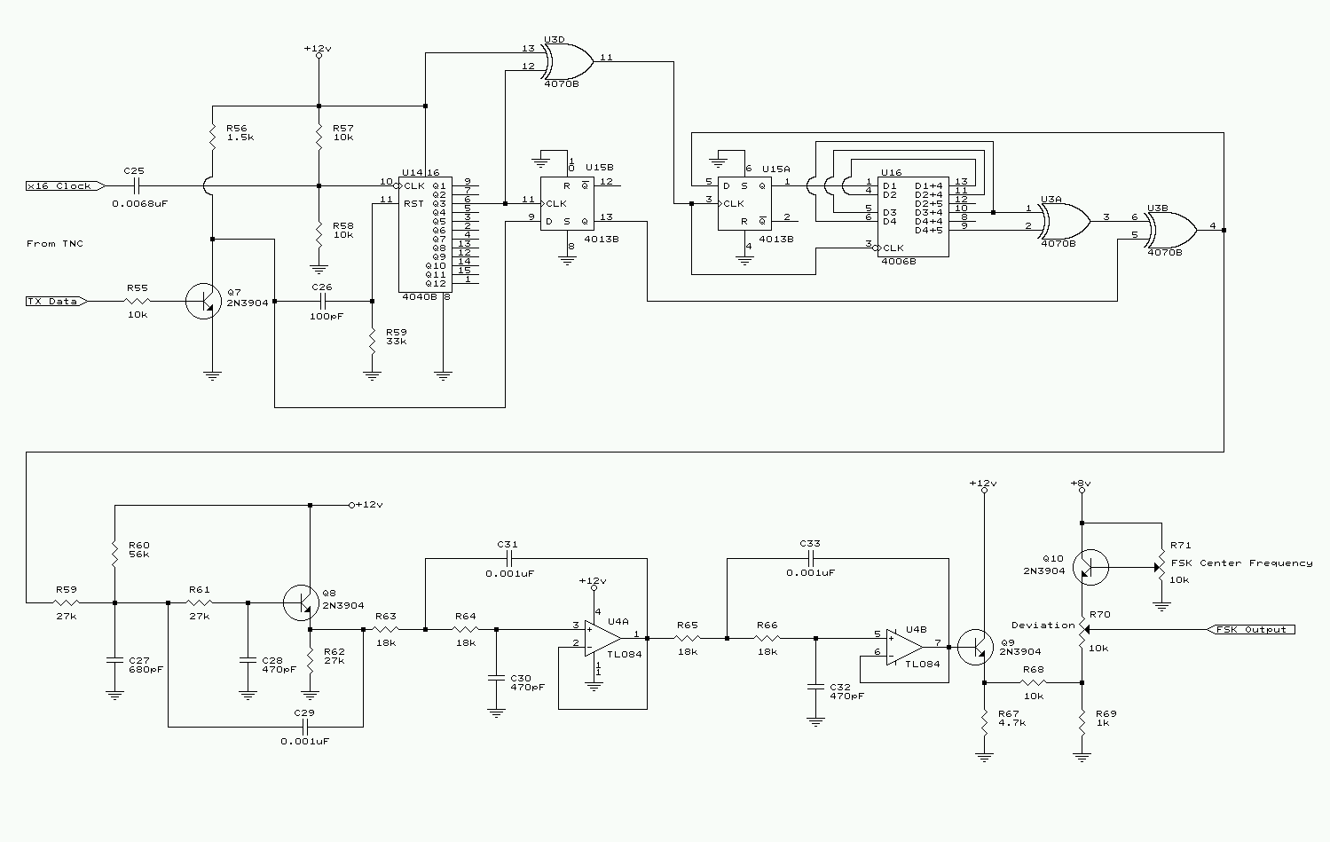
Schematic 4: FSK generation circuitry consisting of an LFSR scrambler and low-pass filter.
 Return to the KD2BD 9600 Baud Modem Page