James Miller G3RUH
Sadly, with the retirement of its champion, declining resources and changing interests the telescope fell into disuse and finally neglect in the '90s. In 1999 the radome blew down in a storm.
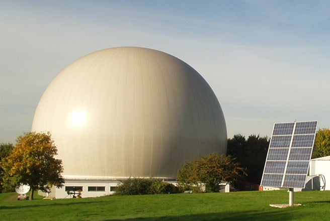
Figure 1. Two kinds of antenna. A general view of the pressurised (5 mbar) dome at Bochum. It's about 40m in diameter. The solar panels are a technology demonstration, and pump a few kilowatts into the electricity grid. (Photo 2003-Oct).
A concerned public rallied around immediately; the state of Nordrhein-Westfalen was approached, agreed to adopt the telescope as an Industrial Monument and provided sufficient funding for its restoration to a safe condition.
The dome was replaced, as well as the pressurisation, space heating and diesel-electric back-up power generation. Public 'outreach' activities were to be provided in return by the curators.
The antenna control arrangements however were long obsolete and beyond practical use. Punched paper-tape based; several racks of electronic modules which, predating integrated circuits, had one logic gate/card; enormous DC motors powered by AC-DC motor-generator sets; enough power switchgear for a small town; that stuff was never going to be revived.
This state of affairs coincided with Amsat-DL needing a substantial ground station for the Phase 5A mission to Mars. Amsat-DL agreed to get the telescope control systems up and running in return for priority use of the dish. Many, many people pitched in to make this happen.
Thus it was that in 2003 the author was invited to write the software to control the telescope. Every ham secretly wants to play with a really big antenna ... here was my chance!
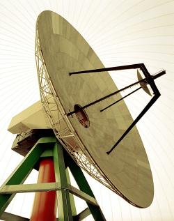
Figure 2. Wide angle view from the floor. The parabola is 20m in diameter, and has an f/d = 0.35. The sub-reflector is 3m in diameter, and the overall focus is at the centre (vertex) of the parabola. Access to the focus room is via a circular stairway inside the azimuth column.
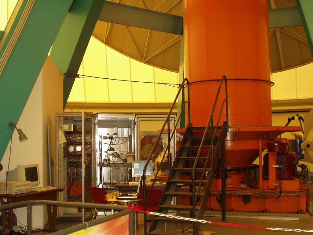
Figure 3. A 140 ton roof over your head. The column is 2m in diameter and rotates on a substantial bearing about 1m in diameter. The LH rack holds 4 servo motor drive amplifiers. The RH rack has the RiscPC (RPC), UPS, GPS and some odds and ends. My personal RPC is on the left being used as a server, holding master copies of the software which was under development at the time. The telescope RPC ran its software fetched across the Ethernet. Finally it was permanently loaded onto the telescope computer for normal use. The electronics in view here essentially replace as much old stuff as would fill a small apartment.
The computer's job is to calculate a desired azimuth/elevation, measure the present azimuth/elevation, determine a suitable current for each motor (which will create the torque) and deliver this current request to the four motor drive amplifiers.
The telescope beamwidth at 10.4 GHz is 0.1°. Thus the objective was set to be able to track with pointing accuracy better than 0.01°. This is achieved at about an order of magnitude better.
The telescope, as seen by the computer, consists of four 19200 baud RS-232 serial lines and a handful of status bits. A pre-existing brand new unused, though 6-year-old 233 MHz StrongARM (DEC/Intel SA-110) RiscPC [10], was augmented with two dual serial port cards and a 16 bit parallel I/O expansion card, and the computer hardware was complete. Precise time information comes from a Jupiter-T GPS timing receiver [3] attached to the standard serial port.
The control computer, called Bocc is also connected by Ethernet to a site management computer called Bomex which is permanently connected to the external Internet. So Bocc telescope control software can be updated remotely, and indeed the telescope also can be operated remotely, with just a couple of clicks, from home.
The site management computer runs Unix (FreeBSD 4.10) and services two cameras, the control computer as above and eventually radio receivers, test equipment and other functions t.b.d., and is maintained by Rainer Rutz DF7DD. [2024: plus others]
Serial port systems never work as advertised, and we had the expected number of gotchas, but at the end of a typically frustrating day one, all the hardware parts were interfacing correctly. Day 2 was then spent getting to grips with the arcane protocols of the motor drive electronics and machinery attached to the serial ports. Fortunately the resident electronic engineer (Hartmut Päsler DL1YDD) had already jumped through these hoops during prior commissioning tests, so borrowing from his Turbo Pascal routines was painless and quick.
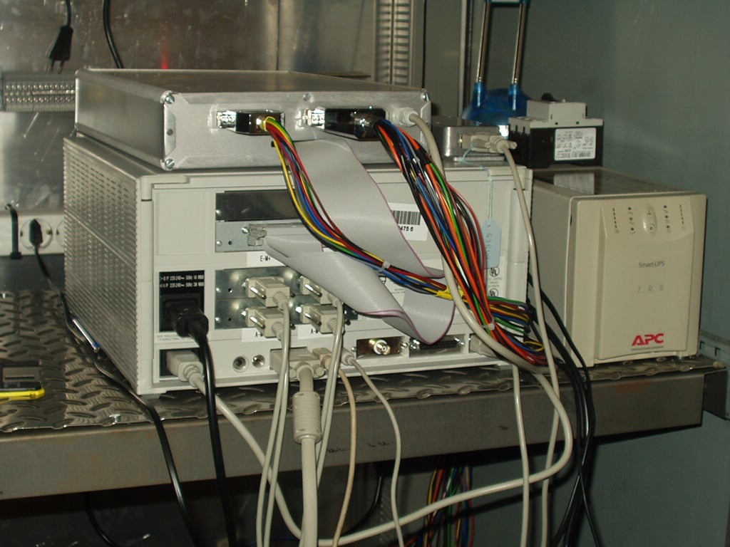
Figure 4. Danger! Non-PC PC at work. Two dual Serial Port cards interface to 4 servo-amplifiers in the LH rack. Top slot has a 32-bit parallel I/O card with ribbon cable to a box above full of opto-isolators and relays. Small box on top is GPS receiver for precise UTC via standard serial port. BNC socket is ethernet connector. To the right is a UPS (uninterrutible power supply).
Many more tests followed. By the end of the day we had a basic working control system which would move the machine with a repeatable accuracy of about 10 arc-seconds. That's the angle subtended by the thickness of a pencil at 150 metres and about an order of magnitude finer than our goal.
The software is written in BBCBASIC, and runs standalone. This is a machine control system, and the computer is not required to do anything else other than its dedicated task. It cycles around a loop 20x per second calculating the desired azimuth and elevation angles, reading the position sensors and computing the required motor drive currents to keep the telescope on track. Next an almanac of the positions all the objects it knows about is updated, one object per loop. The almanac is visible to the operator who can choose the target from it. Finally, servicing the GPS receiver, scanning the keyboard, and displaying engineering data on the screen take but an instant. Doing all this, the computer is about 50% loaded. There is no hardware floating point (f.p.) unit.
After aligning the telescope's azimuth axis to the calibrated datum plate on a wall, the instrument was told to track the Moon. I pressed the button. The machine rumbled into life, and slewed towards the Moon. The radio engineer (Freddy de Guchteneire ON6UG) watched his noise power meter; bang on cue, up came the radio noise level as the Moon swung into the beam.
Some fine calibration of the position sensors was performed, and the telescope was set to point at the very noisy radio star Cassiopeia A. After a few moments the radio noise level increased slightly as the famous super-nova- remnant, which exploded in 1667, came into the beam.
A final test was to track the ESA spacecraft Mars Express then en route to the planet, and 'only' 100 million km distant. The command was given, the telescope slewed to the spot just East of Mars, and when it had settled the receiver was slowly tuned (8.4 GHz) to locate the spaceprobe's telemetry beacon. From the radio came a squeal as the probe's telemetry beacon was tuned in. It had the correct frequency, correct doppler shift profile, and disappeared when the telescope was off-pointed slightly. It was indeed Mars Express. We were in business.
Since then (2003-2005) all the NASA/ESA spacecraft have been regularly tracked, and provide perfect spaceborne beacons for azimuth and elevation calibration, sanity checks, as well as excellent demonstration tools in fulfilment of the observatory's 'outreach' mandate. A feed is also fitted for 1.7 GHz weather satellite reception, with the results available for visitors to watch.
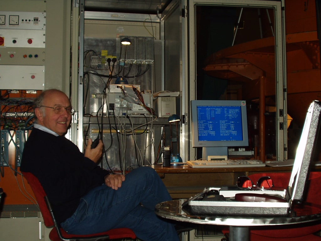
Figure 5. Karl uses a radio. Two of the four Eurotherm motor drive amplifiers can be seen behind Karl Meinzer DJ4ZC; HTs are used for communicating from control room to focus to control racks, and generally around the site.
There are several identifiable elements; plant simulation, servo-controller, and the demand manager. Software implements these and makes the telescope machinery perform as desired.
By applying impulse, step and sinusoidal excitations to the plant simulation, most things of concern can be modelled and discussed. Quite a lot of time was spent exercising this, well before the main telescope package was written. Often a simulation is discarded after use, but in fact this one is very usefully retained, as will be explained.
There is a servo controller routine for each axis. They are similar, differing by constants due to the differing inertias and gear ratios of the machinery. The controller takes the demanded azimuth & elevation, compares them with the measured azimuth & elevation (which is available from the motor drive amplifier units) and computes the required motor current to move the telescope in the optimum way.
Presently the calculations are done at 50 ms intervals (20x per second); this rate is considerably faster than the natural frequencies of the machinery and is set by the speed of calculation of demands.
Testing of the servo-controller was done initially using the previously described Plant Simulation as a substitute for real machinery. In the final software this feature is retained; by the setting of a flag the software can control the real telescope or the simulated telescope; numerically it cannot tell the difference. This allows software development to be continued away from the real instrument.
However, we also had a requirement to compute range-rate of bodies, and I decided at this point to 6-space vectorialise everything, and change the astronomic package over to use the JPL Planetary and Lunar Ephemeris DE405/LE405 [8]. In this the solar system bodies 3-dimensional coordinates are represented by coefficients over a basis set of Chebyshev polynomials. The original JPL Solar System numerical integration, which has formed the basis of professional solar system positional astronomy for many years and of the Astronomical Almanac since 1984, can be recreated to metre-level accuracy with remarkably little calculation. [2021: now JPL's DE440]
This required a rationalisation of everything to do with astro-tracking, and the package is even more accurate and certainly more flexible than it was. It is able to calculate objects' coordinates properly, accounting for the whole litany of small corrections without regarding each as a special case and with various degrees of approximation. These are:
   Light-time correction  (excepting stars)
   Gravitational deflection of light by the Sun
   Aberration          due to velocity of Earth around Sun
   Diurnal Aberration  due to velocity of observer on the Earth
   Parallax            due to observer's position not at Earth's centre
   Annual parallax     due to Earth's position change around Sun
   Precession          Earth's spin axis 25,000 yr circular motion in space
   Nutation            Earth's spin axis wobbly motion in space
   Polar motion        Earth's pole not fixed to ground
That is, "everything". All computations are vectorial, and for the most part in 6-space (3x position + 3x velocity). The detail is documented in [1,2].
After conversion to the observer's horizontal plane, Elevation (including refraction), Azimuth, Range and Range-Rate are output to the user.
This re-organisation took place in 2004 January, and worked perfectly (without even a visit to the telescope).
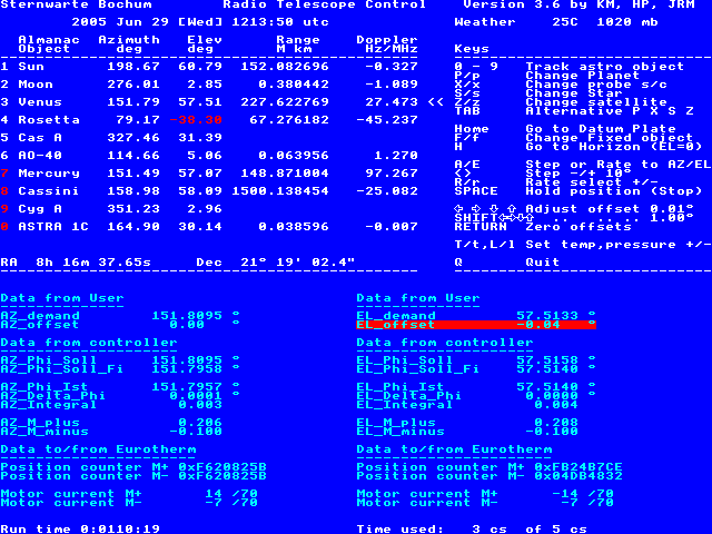
Figure 6. Software screenshot. This is engineering checkout software, so it single tasks and the user interface is straightforward. Later may come multitasking, although for an embedded system there seems little point. Lower half of the screen is diagnostic data from the servo-controller algorithms.
The astronomic algorithms are essentially exact at the 0.05" level. The greatest source of error is incorrect refraction correction (elevation) and timing uncertainties (azimuth). These errors are unlikely to exceed 5".
The following table gives an indication of typical error source magnitude and type:
                                   Typical    Error
 Item   Source                    Magnitude   Type
 ----------------------------------------------------------
  1.    5-byte floating point       0.005"     rms
  2.    Ephemeris calculation       0.05"      rms
  3.    Antenna location            0.05"      bias
  4.    Computer clock              0.2"       az bias max
  5.    Refraction                  5"         el bias max
 ----------------------------------------------------------
For comparison:
* Motor control system is mechanically repeatable in azimuth at the ~10" level.
* Diameter of Mars at closest approach is ~18"
* At X-band (10.4 GHz), the Bochum antenna 0.25 dB beamwidth is 100"
Some notes about the above table:
1. 5-byte floating point: Comparisons with 8-byte floating point arithmetic indicates that provided care is taken with the representation of time, angles are calculated to about 0.000001°. This is negligible uncertainty.
2. Ephemeris calculation: The JPL ephemerides are extremely accurate. The subsequent reduction has some very small simplifications in respect of timescales and axes which introduce the indicated uncertainty. These are orders of magnitude less than more practical matters, and are insignificant. Ephemeris of Earth satellites (via NORAD 2-line elements) are much less accurate than for astronomical bodies, but remain substantially within beamwidth at the 1-2 GHz region typically used.
3. Antenna location: This has been determined using GPS, and is presently well within 1m and improving over time. However dish focus location changes with azimuth and elevation by 1-2m, and this leads to location errors of order 0.05". This error is systematic, and could easily be removed algorithmically.
4. Computer clock: The Bochum telescope software takes UTC from a GPS receiver at regular intervals. The maximum service latency is typically 10 ms, equivalent to an error of typically 0.2", mainly to azimuth. The latency could be reduced to zero by using an interrupt rather than a polling process.
UT1 (for Earth rotation calculation) is taken from IERS Bulletin-A [9] and may be considered exact at our level of interest.
5. Refraction: This is corrected using a model designed for optical observations. The optical formula is accurate to about 5" when more than a few degrees above the horizon, provided temperature and pressure are set correctly. At radio wavelengths humidity enters as a factor and adds between 0 and 10% to the refraction correction over the range 0 to 100% RH, but this is ignored.
Summary: for practical purposes, azimuth and elevation calculations are unlikely to exceed 0.001° at low elevations (below 5°), 0.0001° at high elevations and may be considered 'exact' compared with the required accuracy of 0.01°.
The astronomical routines are kept in a software library, and so are in constant use by support utilities such as forward planning, backward analysis, mission studies, almanac generation and doppler calculation to 1 Hz at X-band. The apparently surplus precision is no disadvantage.
* Dr Peter Duffett-Smith of the Mullard Radio Astronomy Observatory (MRAO) in the University of Cambridge for positional astronomy advice, and sharing algorithms for pre-JPL ephemeris versions (up to v2.3) of the software.
* Dr Karl Meinzer DJ4ZC (University of Marburg) specified the servo controller and the simulator model used in this program, and tuned them to match the telescope dynamics. He is instrumental in pushing along the Amsat programme.
* Hartmut Päsler DL1YDD reverse engineered the Eurotherm motor controller interfaces, and contributed the know-how to make the serial protocols work straight off. He was/is responsible for the electrical refurbishment of the antenna motor systems.
* AMSAT-DL has been the driving force behind the modernisation of the telescope tracking and control system; hardware, software and management.
1. Seidelmann, P.K. (ed), "Explanatory Supplement to the Astronomical Almanac", 1992, University Science Books. ISBN 0-935702-68-7
2. The Astronomical Almanac YYYY. Published annually by USGPO and TSO.
The hard sell:
3. GPS timing unit designed by the author.
Further useful references are:
4. Kraus J.D. "Radio Astronomy", 2nd ed., Cygnus Quasar Books, 1986. ISBN 1-882484-00-2
5. Green R.M. "Spherical Astronomy", Cambridge University Press, 1985. ISBN 0-521-31779-7
6. Meeus, Jean, "Astronomical Algorithms", 2nd edition 1998, Willmann-Bell Inc. ISBN 0943-3966-61-1
7. Heafner, P.J., "Fundamental Ephemeris Computations", Willmann-Bell Inc. 1999. ISBN 0-943396-63-8
Astronomic data:
8. The JPL Horizons on-line ephemeris generator provides high precision data with which to check the astronomic algorithms.
9. IERS Bulletin A contains dAT and dUT offsets, as well as polar motion.
Even harder sell:
10. The Acorn RiscPC is no longer produced, but is still available.
Feedback on these pages to Webmaster. Feedback on the article should be sent to James Miller
Page created: 2005 Dec 02 -- Last modified: 2024 Oct 02 [ minor updates ]