James Miller G3RUH
Data links too have limits, and many strategies exist to deal with them. For example, packet radio links use ARQ; a packet of data contains a checksum, and corruption in transmission is easily detected and a repeat can be requested. But not all links are bi-directional; examples include CDs, digital radio/TV; and spacecraft telemetry systems.
A familiar example is Oscar-40 400 bps telemetry. Data is sent in 512 byte blocks with a checksum. But if just one bit in the block is corrupted due to noise or spin fading, then the block is useless. A checksum detects the existence of error(s), but nothing can be done to locate or correct them. Thus the telemetry beacon needs to have a very strong signal. This defines the required beacon radiated power and ground station antenna size.
In fact, the simple conventional format of Oscar-40 telemetry, even when operating at its threshold of performance, demands a signal some 10x stronger than is actually required for error-free communication. See figure 1.
Figure 1. FEC offers some 10 db improvement over conventional AO-40 telemetry. At an Eb/No of 1 db it is barely audible, yet decodes perfectly. Notice the steepness of the FEC plot; 1 db span covers perfection to oblivion.
In the AO-40 experiments, only the active 256 bytes of the A-block are processed because it represents all the spacecraft's operational data.
Figure 2. Channel symbol errors on a typical orbit averaged over each MA interval. The spacecraft antenna's first null is apparent at squint angles 38-55°, the first sidelobe is from 55-80°. At 90° the spacecraft is sideways-on, and after that the antenna is masked; signals are very weak and choppy, but often decode. Key features in this profile translate into squint angle measurements and are even used for attitude calculations.
If smaller antennas are your interest, then signals from the patch antenna seen in figure 3 will provide error-free telemetry throughout most of the orbit, weakening when the pointing angle (squint) is around 40-55° which is the spacecraft antenna's first null and signals have a tendency to vanish.
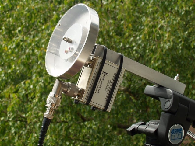
Figure 3. This RHCP patch has a gain of 8.5 dbic and a 3db beamwidth of nearly 90°. Its signals decode through most of an AO-40 pass, and with the wide beamwidth it only needs re-pointing every few hours.
If you want an ultra-small antenna, then since you can hear the AO-40 beacon on a ground plane figure 4, signals will often decode successfully. For this, the squint angle needs to be under than 15°, and the range preferably 50,000 km or less.
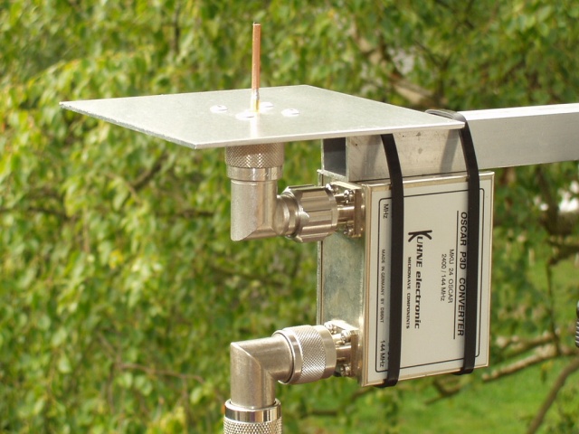
Figure 4. Small is beautiful. The AO-40 beacon is often just audible on this. Using FEC, if you can hear it, you can decode it. So the FEC telemetry often decodes.
Join your thumb and forefinger, and try to imagine how much spacecraft energy passes though the hole, because that's what's being processed. This is a remarkable result whichever way you look at things and there is scope for a lot more experimentation with very small antennas.
Essentially we wish to combat two factors that introduce errors; spin modulation/fading and weak signals. Of these, spin modulation is responsible for the greatest destruction of telemetry.
Then, given that residual errors will still occur, we want to detect, and if possible, correct them.
In this experimental phase, FEC is applied to the second 256 bytes of the A-block only. This contains all the spacecraft analogue and digital housekeeping data. These 2048 bits are processed as will be described which expands them to 5200 bits, for which the proper term is 'symbols'. The encoding process is illustrated in figure 5.
Figure 5. FEC encoding takes 256 bytes in and creates a block of 650 bytes (5200 bits) ready for the beacon to transmit. See text.
The source data is divided into two halves of 128 bytes each and enter two Reed Solomon (RS) encoders which add 32 parity bytes each. Since the original data is present in the RS blocks, and typically contains undesirable systematic features such as runs of 0s, they are eliminated using a scrambler/randomiser.
The parity protected data now enters a convolutional encoder which emits 2 bits for every bit entering. After a final flush to the all-zero state, a 65 bit sync vector is introduced, plus 3 spare bits, and a total of 5200 bits is deposited into the interleaver array ready for transmission on-air.
Figure 6. FEC decoding reverses the operations of the encoder. The de-interleaver compensates for fades, the Viterbi decoder corrects most symbol errors, and the RS decoders detect and correct residual errors.
The stream of apparently random symbols is searched for the 65 bit sync vector. This is distributed throughout the 5200 symbol block, at every 80th bit position. When detected by a comparison (or correlation) process, the block is delineated and decoding the data can begin.
The primary defence against spin modulation/fading is a block interleaver, figure 7. The 5200 bits are arranged in an 80 columns x 65 row grid. Bit-stream data as received is deposited along the rows, row after row. But it is read out for processing by column. In this way a fade, which may span several rows, is smeared thinly by the read-out process, and its effects are easily dealt with by the error correction systems.
Figure 7. The interleaver holds 5200 bits. They are transmitted (and received) along the rows but are read out down the columns. Thus long fades, such as the one illustrated, only affect a few bits at a time in the read sequence, and are easily corrected by the Viterbi decoder.
The next defence against channel errors, which are now (hopefully) evenly spread throughout the de-interleaved block is the convolutional code, figure 8. At the transmitter, each original bit entered a convolutional encoder, and gave rise to a pair of new symbols.
Figure 8. The simple structure of a convolutional encoder, which can be implemented in hardware with a shift register and some EXOR gates, or the equivalent in software. The constraint length K of 7 implies that a bit entering has an influence over 14 output symbols as it progresses down the shifter. The inverter prevents long runs of zero output.
The Viterbi convolutional decoder, named after its inventor, attempts to re-construct the original bit sequence given the fact that successive symbol pairs are related to their 12 predecessors. An elegant description of the Viterbi decoder is available at [4], and design information can be found in any book entitled "Digital Communications". It is an interesting and straightforward algorithm. The decoder can work at about a 10% input symbol error rate without making errors itself. Thereafter mistakes do happen, and small bursts of errors are emitted, which corrupt one or two bytes.
Final error detection and correction is done using Reed Solomon (RS) decoding. Whereas a standard telemetry block has a simple 2-byte checksum appended, adequate to detect errors but not correct anything, RS encoding appends many checking bytes. In the AO-40 system the additional 25% bytes (64) mean up to 32 bytes (actually 16+16) can be corrected per telemetry block. RS decoding is quite a complex process which exploits the number-theoretic properties of the encoding modulo-255 arithmetic. The classic description can be found at [2], but this is essentially a postgraduate text. I have not yet located a layman's guide.
If the block decodes without errors, as it usually does, then it is easy to re-encode the block and compare the expected symbols with those actually received. In this way a count of the number of channel symbol errors is obtained.
Overall, the Viterbi convolutional and RS block decoders working together can cope with up to 15% channel errors, or as many as 750 symbols (bits) per block. Decoding time depends on processor speed, and is of order 10/MHz seconds per block assuming a "C" program. For example, a 500 MHz processor would decode an FEC block in typically 20ms.
So for the initial trials the IHU-2 monitors the IHU-1 telemetry stream, captures any A-blocks therein, and performs the FEC encoding. The encoder is written entirely in IPS, and takes 100ms to execute. A reference encoder is at [5].
The IHU-2 beacon handler has been modified to send not only the standard telemetry A-block, but an additional 5200 bits, the FEC material. Thus the user receives the original data and its FEC equivalent every 27 seconds. This FEC mode is switched on frequently.
Getting from received audio to decoded data requires a signal processing chain which is implemented using various combinations of hardware and software. A reference FEC decoder is at [6].
There are many options for changes to hardware and software, and gradually they are being implemented. Here are some of them.
An important change is required of all PSK decoder implementations; it is that bit detection must no longer be based on a simple binary slicer. It helps the convolutional decoder to know whether bit detection was strong or weak. A slicer discards that information and implies all bits equally strongly detected; but in the presence of noise this is not true; some bits are more confidently detected than others, and this needs to be passed to the Viterbi decoder. The penalty for ignoring detection quality information is up to 2 db decoding loss, an undesirable waste of performance. Thus hardware PSK decoders, and soundcard/DSP-based PSK decoders must be modified to meet this requirement.
An analogue-to-digital converter kit is available for the G3RUH 400 bps PSK Data Demodulator hardware. This takes the output from the bit detector, digitises it to 8-bit resolution, and sends one byte per bit at 9600 bps down an RS232 serial port [7].
Soundcard DSP software is also being modified at the bit detectors; recent software has it anyway, e.g. Phil Karn KA9Q's for Linux [8].
FEC decoding can be done either by off-line processing which converts FEC blocks into conventional blocks, or it can be done in upgraded telemetry display programs.
The popular telemetry display program P3T for Windows by Stacey Mills W4SM has been upgraded to take serial data from a serial port ADC and decode the FEC format. Work is also in hand to add a soundcard PSK decoder module adapted from the design of Moe Wheatley AE4JY and others. P3T can also display telemetry logs created by other systems which may already have performed FEC decoding.
1. "Proposal for a FEC-Coded AO-40 Telemetry", Karn P., Proc. 20th Amsat Space Symposium, 2002. (See [3])
2. Error Control Coding: Fundamentals and Applications", Lin and Costello, Prentice Hall, 1983, ISBN 0-13-283796-X (2nd edn. ISBN 0-13-042672-5)
4. Description of Viterbi. (Scroll down ~40% to para before "Information Coding: Varicode")
7. ADC Kit
Feedback on these pages to Webmaster. Feedback on the article should be sent to James Miller
Page created: 2005 Oct 30 -- Last modified: 2023 Apr 23 [ URLs]