James Miller G3RUH
My purpose is to show that the subject is not a Great Mystery, but is really quite straightforward and for all to share. My mail indicates that for many, understanding the birds is as much fun as transponding via them. Most of these notes are specific to single axis determination for near- Earth, spin-stabilised satellites.
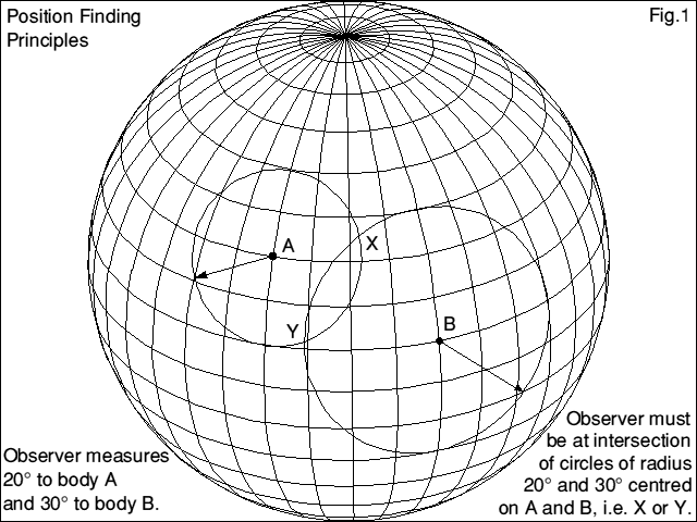
Suppose for example we have two objects, body A and body B, and we determine that body A makes an angle of say 20° with respect to our vertical (say), and body B say an angle of 30°.
Then we (or rather our vertical) must lie somewhere on a circle radius 20° about the known position of A, and a circle radius 30° about B. Our position must be where the circles intersect. Obviously two circles can overlap at two points, so this ambiguity needs resolving, either by an observation of a third body, or by using some prior knowledge.
It doesn't matter whether these circles are drawn on a flat sheet of paper such as a map or as arcs on a sphere. Figure 1 illustrates the point on a globe, which as we shall see also represents the bird's eye view of the heavens.
For a near-Earth spacecraft we have the Sun, stars, Moon and the Earth itself. The thing which is important about all these objects is that their position is known precisely. The choice of which to use is determined by the spacecraft's mission, and the attitude fix accuracy needed.
A thing to bear in mind from now on concerns the spacecraft's orientation. The satellite is not tumbling about all over the place. On the contrary, it is spinning at a steady rate about the main axis of symmetry, and provided it's not being magnetorqued this spin axis points at the SAME PLACE in the sky all the time. Oscar-10 itself may be trundling round the Earth, but the spin axis is fixed for weeks on end, roughly parallel to the orbit major axis.
The optical sensors are mounted in the end of arm 2, and they look out on what is called the spacecraft's equator. So the sensors scan the equatorial belt once per revolution, about 30 times a minute.
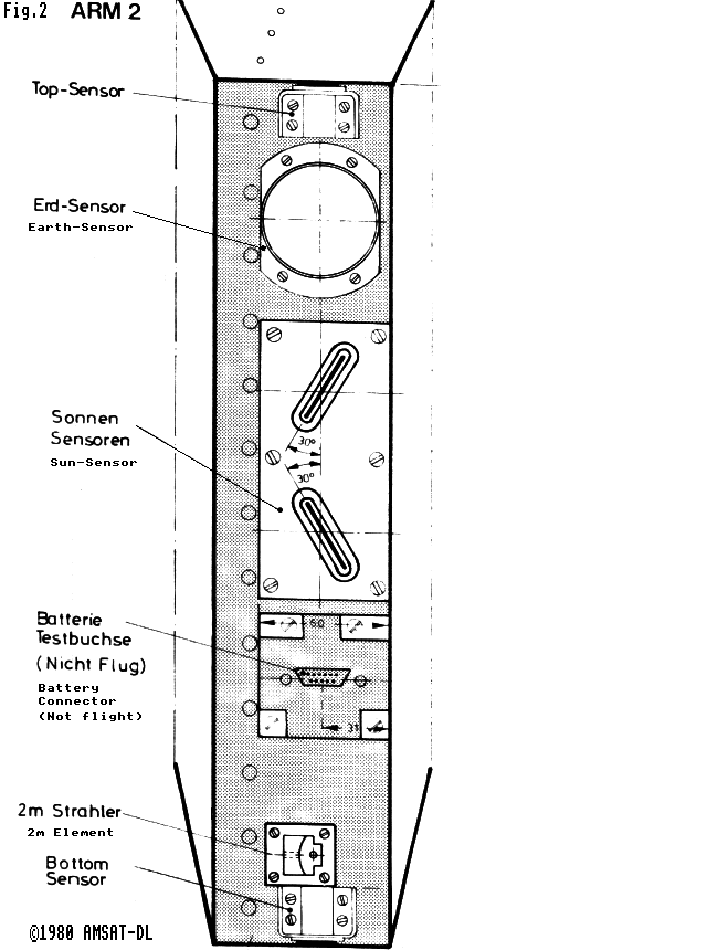
Figure 2 is an end view of sensors, reproduced from PHASE IIIb drawing number 3076A. The circular Earth sensor has a lens and a projecting hood (like a camera) acting as a sun shade. The Sun sensor actually comprises two identical units mounted as shown.
Oscar-10 carries two other sensors, solar cells 20mm x 20mm facing top and bottom. These give instant qualitative indications as to whether the Sun is above, below or on the spacecraft equator - as also do the top and bottom temperature sensors. Their main function is as a safety stop; the on board computer will immediately turn off the transponders and magnetorquers if the Sun comes too far (50°) above the S/C equator.
On Oscar-10 this slit is 33 mm x 0.6 mm, with the BPX48 diode 5 mm behind. Allowing for obstructions, this gives the diode a field of view of about +/-60°.
As the satellite spins the sun flashes past the slit once per revolution, giving a 'pip' or pulse from the photodiode electronics at the precise moment the Sun passes through the field of view.
Both Sun sensors give pips, but you can see from figure 2 that each is inclined 30° to the spin axis, or 60° to the equator. So the pips will occur at slightly different times. It is this difference which provides the measurement of 'Sun Angle'. Sun Angle is defined as the angle between the Sun and the Satellite's equatorial plane. Figure 3 shows how.
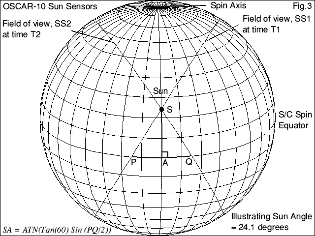
At instant T1 the upper sensor, called SS1, pips, so its field of view must be arc SP. A moment later at T2 the lower sensor pips, and its arc is SQ. If we know the baseline angle PQ and, as each arc is inclined at 60°, we can solve for the triangle for sun angle SA, viz: SA = ATN(Tan(60)*Sin(PQ/2) ).
In outline it consists of an oscillator which is phase locked to the upper beam (SS1) pips. The oscillator runs at 256x the pip rate and drives an 8-bit counter. So the counter reads 0 when SS1 pips. When the lower beam (SS2) pips the counter state is read into the on-board computer's telemetry buffer.
In this way the equator is divided into 256 parts and the arc PQ is now 360*SS2Count/256°, making the sun angle conversion equation:
SA = ATN(Tan(60)*Sin(180*SS2count/256)), all in degrees.
Counts exceeding 127 represent a negative value of PQ, i.e. use 256-SS2count. 1 count is equivalent to about 1.2°. The spin counter is also read when SS1 pips; if the system is properly synchronized, SS1 will read 0 (or in fact 255 - the loop must dither).
The instantaneous spin count (ISC) is however telemetered, and you can determine spin rate precisely; to within 1 count in a minimum interval of one telemetry block (26 seconds) giving 0.03% accuracy, or say 30 minutes or more for a few parts per million. For example, on orbit 1481, 1985 Jun 02 I noted:
         HHMM:SS.ss     REV     SC
         ---------------------------
         0450:17.14     0       125
         0450:52.98     18      128
         0451:20.36     32       68
         0451:47.30     45      206
         0452:14.26     59       91
         ---------------------------
The time between first and last is 117.12 seconds, and the spin counter has incremented (59*256 + 91) - (0*256 + 125) = 15070 counts, giving a rate of 128.67 counts per second, i.e. 60*128.67/256 = 30.16 r.p.m. The catch, however is that the whole number of spin revolutions (REV in the table) is not telemetered, so it has to be inferred by taking an initial estimate (stopwatch, spin-modulation, timing of).
I carried out the experiment for 30 minutes on several successive days, and found that spin rate was gradually falling, at a somewhat variable rate averaging 0.007 r.p.m per day. Faster spin rates were sometimes found at perigee, compared with apogee. Any suggestions?
Remembering 'Principles', if the Sun is angle SA up from spacecraft equator, then it means the satellite spin axis must be lie somewhere along a circle radius 90-SA centred on the Sun's position.
In the opening remarks I said "observations of two or more bodies" were needed. Specifically we need any object not located at the same position as the first. This thing might be the Earth, but it could equally be the Sun some days later when it will have moved. I shall demonstrate with two actual observations. They were:
       YEAR    DAY     GMT     SUN ANGLE
       ----------------------------------
       1985    152     0639     -2.43 deg
       1985    169     0340    -16.49 deg
       ----------------------------------
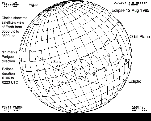
In Oscar-10 coordinates positive Sun angles mean the Sun illuminates the spacecraft bottom or motor side. Negative angles are on the top or high gain antenna side. The spacecraft spin direction is clockwise viewed from the top. Figure 4 shows the resulting attitude solution graphically.
It represents the spacecraft's view of the heavens, expressed in orbit plane coordinates. These are drawn on the diagram. You are to imagine that you (Oscar-10) are located inside this sphere, and the grid is engraved all around you on the sky at 20 degree intervals. The spin axis points out of "Soln. 2", and the sensors therfore scan a circle 90° away from this marked "S/C Equator (soln. 2)".
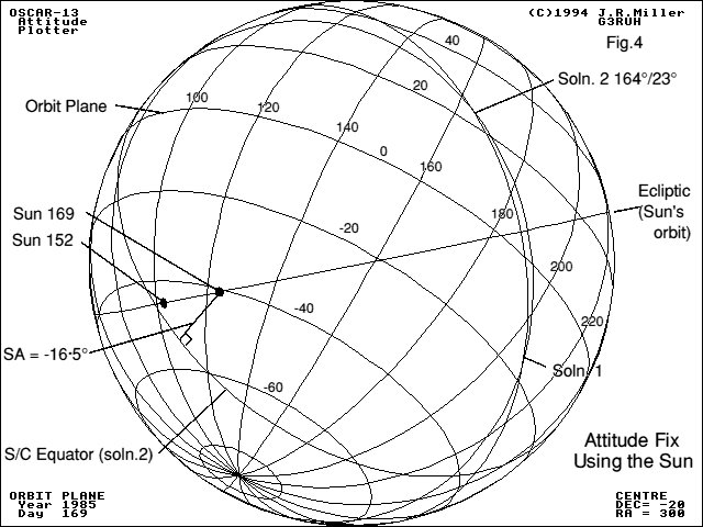
The two arcs intersect as shown at the two potential attitude solutions, marked as Soln. 1 and 2. Note that they are equispaced across the Sun's plane or Ecliptic.
To resolve this ambiguity we need more information. Further Sun arcs won't help, as they will simply intersect the solutions at the same place. A body not in the plane could be used - such as the Earth. However there is an easy way, using your ears again.
The attitude axis is the same as the spacecraft antennas'. So by listening to the beacon strength, and spin modulation characteristics you can compare what you hear with what would be expected in each case. Here, Soln. 1 would have given very large pointing errors (squint) which was not observed, whereas Soln. 2 correlated very well with expectation, so must have been the true attitude solution.
The solution values can be read off the globe as DEC = 19°, RA = 329°. These values are constant. In orbit coordinates they become longitude 164°, latitude 23° below plane; but they will change slowly with time as the orbit plane moves (precesses).
Put another way, if you could stop Oscar-10 at apogee, sit on the orbit plane and peer along the antenna axis, you would be looking slightly below and to the right of the Earth, whilst the Sun would be burning a hole in your right shoulder.
So in practice you have to take more than two measurements, and validate them carefully. A batch of measurements can be treated graphically but it is quicker and easier to do a numerical analysis by computer.
The intersection angle can also be increased by taking data over a longer interval. - BUT it means you cannot get an instant attitude solution when you need one quickly, particularly when manoeuvring the spacecraft.
The solution to this is to use another body altogether. Next time I will describe the Earth Sensor subsystem, and how it is used together with the Sun instrument, to give a quicker fix.
Oscar-10 Operating Handbook, AMSAT-UK, London E12 5EQ. Should be on every user's shelf, and essential for the telemetry spec.
Special thanks to Oscar-10 Commander Ian Ashley ZL1AOX, for verifying this article's facts exceptionally promptly.
All BBC computer generated graphics ©1985 G3RUH. [Redrawn 1994].
You will remember that an attitude fix needs us to take one measurement each of two non-coincident bodies. Since the Sun is in a different position at any two different times it can offer (via the Sun Sensor) sufficient data for the job. However using the Sun sensor alone needs data gathered over an interval of a week or more if sufficient accuracy is to be achieved. This is fine when the satellite is not being moved to take up a new attitude, but during manoeuvres a quicker method is needed.
This is where the Earth sensor comes in, since the satellite invariably sees it in a different position from the Sun (except during eclipses!).
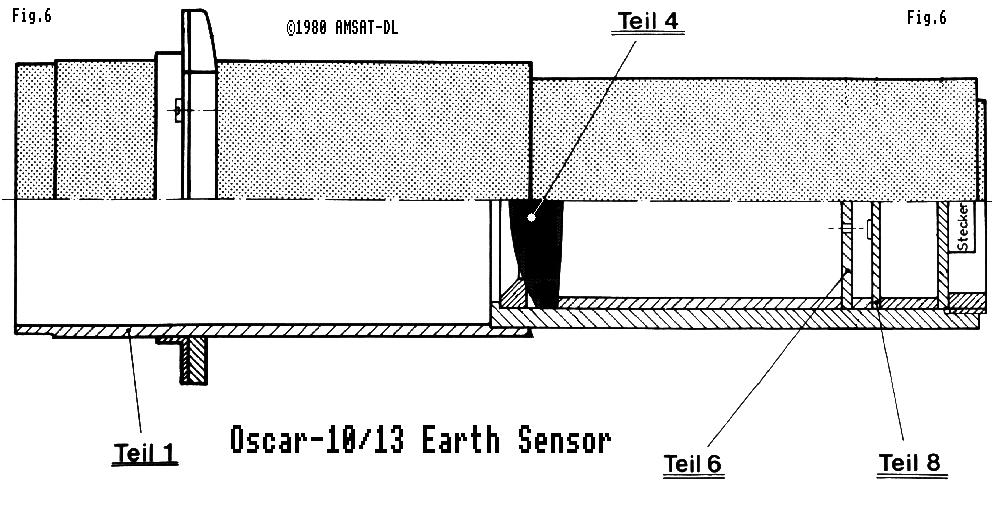
Figure 6 is a cross section of OSCAR-10's Earth sensor optics, and is reproduced from AMSAT Phase 3b drawing number 6003. Light enters from the left via an anti-glare shield (1) and the radiation-resistant lens (4), which has a focal length of about 65mm. Two photodiodes are mounted at the focus on plate (8), and just in front of the diodes is a disc (6) with two 2mm holes in front of the diodes, 5mm above and below the centre. This creates two Earth sensors, in one package. Each has a beamwidth of 2°, and they 'look' 4.4° above and below the main axis. The field of view is limited by the shield, and is about +/-13°.
The instrument, like the Sun sensor is mounted looking out of arm 2. As Oscar-10 moves around its orbit, shortly before perigee Earth will come into the sensors' view, and an image of the Earth sweeps across the photodiodes. One or both photodiodes will give out a signal, commencing at horizon-in, and ceasing at horizon-out. The time of start (or finish) of this signal gives us the measurement we need. Gradually the Earth comes into full view, then leaves. Shortly after perigee, depending on the exact orientation of the spacecraft, Earth once more comes into view, giving a second series of measurements.
Figure 7 shows the geometry. Oscar-10 is at the centre of this sphere, its spin axis vertical, with the motor pointing out at 'A'. Both Sun and Earth sensors look out onto the equatorial belt, scanning round from left to right as Oscar-10 spins. The Earth's disc is shown centred at 'E', and the lower (motor) Earth sensor beam is shown intercepting the horizon at Hin, leaving at Hout. The upper (antenna side) sensor will not be triggering. Also shown is the position of the Sun, at 'S'. During an encounter the Earth moves essentially up or down this figure.
The same clock is used by the earth sensor electronics; a register is clocked with the instantaneous spin count at either Hin or Hout, depending on the setting of the ground-controlled Edge Select Flag. So the Earth sensor measurement is simply the angle 'BH', expressed in 256ths of a revolution. In the jargon this is known as a 'rotation angle' measurement, while the Sun sensor provides an 'arc-length' measure SB.
As there are two Earth sensors, so two values are telemetered; however a flag is also needed so say whether the ES measurement has just been updated or not. The flag is reset as the spin counter goes through zero on each revolution. Also telemetered are the mean anomalies corresponding to each measurement. In summary, the ES system provides ESL, MAL, FLL and ESU, MAU and FLU (sensor count, mean anomaly, flags; lower/upper).
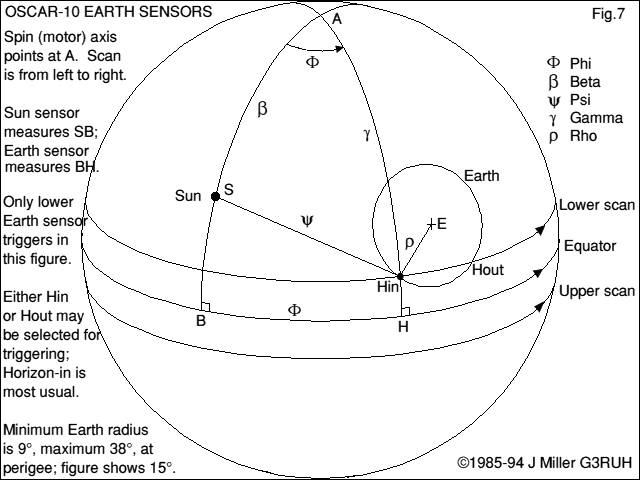
Let's work backwards from the solution. 'A' is at the intersection of two arcs of known length, beta (β) and gamma (γ), though we don't yet know where point Hin is. However, Hin lies at the intersection of two known arcs rho (ρ) and psi (ψ), but we first need to know the length of psi (ψ). The latter is the third side of triangle S-A-Hin, for which we already know angles S-A, A-Hin and the included angle phi (φ), which is the same as B-H, the Earth sensor measurement.
This is a purely geometric problem, and takes no account of whether the earth was actually illuminated at the time, or whether the sensor trigger could have been a terminator crossing, so additional checks are applied to the potential solution to ensure that the answer is reasonable. The process actually gives two solutions for each sensor - try it with a ruler and compass, 'flattening' figure 7 as it were.
During an Earth encounter a whole series of changing measurements can be obtained, so one can plot a graph of ES versus MA, weed out the duff observations, and generate some smoothed measurements for processing.
   OSCAR-10 ATTITUDE DETERMINATION
   -------------------------------
   Which Earth Sensor; [U/L] ? LOWER

   YEAR 1985 DAY 255   ORBIT 1691
   SS1  0    SS2  217
   ESL  158  ESU  169      Earth's appearance - Full
   MAL  253  MAU  250      Solution condition - OK. Horizon wholly lit

            Soln      Dec        RA      ALAT      ALON  Horiz
         --------------------------------------------------------
             1       -55.4     355.4     -32.0     203.2  Hout
             2         1.0      41.7      26.7     238.8  Hout
         --------------------------------------------------------

   OSCAR-10 ATTITUDE DETERMINATION
   -------------------------------
   Which Earth Sensor; [U/L] ? UPPER

   YEAR 1985 DAY 255   ORBIT 1691
   SS1  0    SS2  217
   ESL  158  ESU  169      Earth's appearance - Gibbous
   MAL  253  MAU  250      Solution condition - OK. Horizon crossing lit

            Soln      Dec        RA      ALAT      ALON  Horiz
         --------------------------------------------------------
            1       -55.5     347.1     -33.6     197.9  Hout
            2       -29.9      37.6      -3.8     232.3  Hout
        --------------------------------------------------------
Comparing the four results we could be fairly confident that Oscar-10's attitude was latitude -33°, longitude 200° (in-plane coordinates). This implies that in a view from apogee, the antennas would be pointing up and to the left of the Earth. Another few measurements would confirm this result.
©1985 J R Miller G3RUH
Feedback on these pages to Webmaster. Feedback on the article should be sent to James Miller
Created: 1994 Dec 09 -- Last modified: 2023 Jul 05